Clearance hole chart for metric and inch screws
A clearance hole is slightly larger than the screw so it passes through without threading. Per ISO 273, an M6 screw takes a 6.4 mm close, 6.6 mm normal or 7 mm loose hole; an M4 takes 4.3, 4.5 or 4.8 mm. For inch screws, drill #9 close or #7 free for #10, and letter F close or 17/64 in free for 1/4 in.
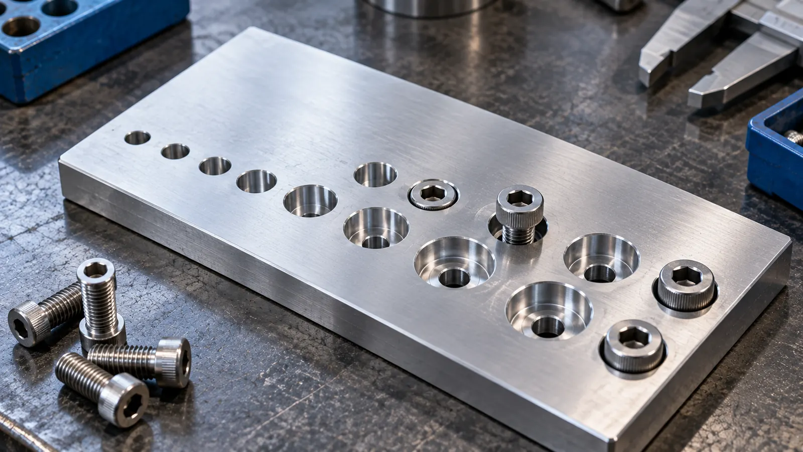
Key takeaways
- ISO 273 gives three metric clearance fits: close (fine), normal (medium) and loose (coarse).
- Use normal fit by default; an M8 normal clearance hole is 9 mm.
- Inch close fit is at least 0.004 in or 2 percent over the screw diameter; free fit at least 0.010 in or 5 percent over.
- A #8 screw clears through a #18 drill (close) or #16 drill (free).
- Metric countersunk screws use a 90 degree countersink; inch flat head screws use 82 degrees.
Clearance hole chart: what a clearance hole is
A clearance hole is a hole slightly larger than a screw or bolt, so the fastener passes through one part and threads into the next. The hole itself carries no thread. In metric work the sizes come from ISO 273, which gives three fits for each screw: close (fine), normal (medium) and loose (coarse).
The bolt clearance hole size chart below shows all three. An M6 screw, for example, takes a 6.4 mm close hole, a 6.6 mm normal hole or a 7 mm loose hole. The difference between hole and bolt is the clearance. Half of it, the clearance per side, is how far the parts can shift before the bolt touches the hole wall.
Clearance holes are different from tap drill sizes, which are smaller than the screw so a tap can cut threads, and from pilot holes for wood screws and lag screws.
Metric clearance hole chart (ISO 273)
For general metric work use the ISO 273 normal (medium) fit. Use close fit when the bolts also locate the parts, and loose fit for long hole patterns, welded frames or castings.
| Screw | Close (fine) mm | Normal (medium) mm | Loose (coarse) mm | Normal fit in inches |
|---|---|---|---|---|
| M1.6 | 1.7 | 1.8 | 2 | 0.071 |
| M2 | 2.2 | 2.4 | 2.6 | 0.094 |
| M2.5 | 2.7 | 2.9 | 3.1 | 0.114 |
| M3 | 3.2 | 3.4 | 3.6 | 0.134 |
| M3.5 | 3.7 | 3.9 | 4.2 | 0.154 |
| M4 | 4.3 | 4.5 | 4.8 | 0.177 |
| M5 | 5.3 | 5.5 | 5.8 | 0.217 |
| M6 | 6.4 | 6.6 | 7 | 0.260 |
| M8 | 8.4 | 9 | 10 | 0.354 |
| M10 | 10.5 | 11 | 12 | 0.433 |
| M12 | 13 | 13.5 | 14.5 | 0.531 |
| M14 | 15 | 15.5 | 16.5 | 0.610 |
| M16 | 17 | 17.5 | 18.5 | 0.689 |
| M18 | 19 | 20 | 21 | 0.787 |
| M20 | 21 | 22 | 24 | 0.866 |
| M22 | 23 | 24 | 26 | 0.945 |
| M24 | 25 | 26 | 28 | 1.024 |
| M27 | 28 | 30 | 32 | 1.181 |
| M30 | 31 | 33 | 35 | 1.299 |
| M33 | 34 | 36 | 38 | 1.417 |
| M36 | 37 | 39 | 42 | 1.535 |
| M39 | 40 | 42 | 45 | 1.654 |
| M42 | 43 | 45 | 48 | 1.772 |
| M48 | 50 | 52 | 56 | 2.047 |
The most searched sizes, read straight from the table:
- M3 clearance hole: 3.2 mm close, 3.4 mm normal, 3.6 mm loose.
- M4 clearance hole: 4.3 mm close, 4.5 mm normal, 4.8 mm loose.
- M5 clearance hole: 5.3 mm close, 5.5 mm normal, 5.8 mm loose.
- M6 clearance hole: 6.4 mm close, 6.6 mm normal, 7 mm loose.
- M8 clearance hole: 8.4 mm close, 9 mm normal, 10 mm loose.
- M10 clearance hole: 10.5 mm close, 11 mm normal, 12 mm loose.
- M12 clearance hole: 13 mm close, 13.5 mm normal, 14.5 mm loose.
The ISO 273 sizes are hole diameters, not drill names. Metric jobber drills step by 0.1 mm from 3 mm, so every size up to 26 mm is a stock drill. The larger sizes are usually made with a step drill, a core drill or by interpolating with an end mill.
Inch screw clearance hole chart (#2 to 1 in)
For inch screws, a close fit is about 0.004 to 0.006 in over the major diameter on small sizes, and a free fit about 0.010 in or 5 % over. The chart below applies that rule to the standard number, letter and fractional drills of ASME B94.11M.
How the table is built, so it can be checked or extended: the close-fit drill is the smallest standard drill at least D + 0.004 in, or D + 2 % of D when that is larger. The free-fit drill is the smallest standard drill at least D + 0.010 in, or D + 5 % of D when that is larger. D is the screw's basic major diameter. The last column is the smallest fractional bit that meets the close-fit allowance, for anyone with only a fractional drill set. Values are a calculated shop practice, not a copy of ASME B18.2.8, the inch clearance-hole standard; where a drawing calls out a hole size, the drawing wins.
| Screw | Major dia. in | Close fit drill | Free fit drill | Fractional-only bit |
|---|---|---|---|---|
| #2 | 0.0860 | #42 (0.0935) | #41 (0.0960) | 3/32" (0.0938) |
| #4 | 0.1120 | #32 (0.1160) | 1/8" (0.1250) | 1/8" (0.1250) |
| #6 | 0.1380 | #27 (0.1440) | #25 (0.1495) | 5/32" (0.1562) |
| #8 | 0.1640 | #18 (0.1695) | #16 (0.1770) | 11/64" (0.1719) |
| #10 | 0.1900 | #9 (0.1960) | #7 (0.2010) | 13/64" (0.2031) |
| #12 | 0.2160 | #2 (0.2210) | #1 (0.2280) | 15/64" (0.2344) |
| 1/4" | 0.2500 | F (0.2570) | 17/64" (0.2656) | 17/64" (0.2656) |
| 5/16" | 0.3125 | P (0.3230) | 21/64" (0.3281) | 21/64" (0.3281) |
| 3/8" | 0.3750 | W (0.3860) | X (0.3970) | 25/64" (0.3906) |
| 7/16" | 0.4375 | 29/64" (0.4531) | 15/32" (0.4688) | 29/64" (0.4531) |
| 1/2" | 0.5000 | 33/64" (0.5156) | 17/32" (0.5312) | 33/64" (0.5156) |
| 9/16" | 0.5625 | 37/64" (0.5781) | 19/32" (0.5938) | 37/64" (0.5781) |
| 5/8" | 0.6250 | 41/64" (0.6406) | 21/32" (0.6562) | 41/64" (0.6406) |
| 3/4" | 0.7500 | 49/64" (0.7656) | 51/64" (0.7969) | 49/64" (0.7656) |
| 7/8" | 0.8750 | 29/32" (0.9062) | 59/64" (0.9219) | 29/32" (0.9062) |
| 1" | 1.0000 | 1-1/32" (1.0312) | 1-1/16" (1.0625) | 1-1/32" (1.0312) |
What size drill bit for a #8 screw?
A #8 screw has a major diameter of 0.164 in. For clearance, drill #18 (0.1695 in) for a close fit or #16 (0.1770 in) for a free fit. With a fractional set, 11/64 in (0.1719 in) works. This is the 8-32 clearance hole size. To tap an 8-32 thread instead, use the #29 tap drill.
What size drill bit for a #10 screw?
A #10 screw is 0.190 in. Drill #9 (0.1960 in) for a close fit or #7 (0.2010 in) for a free fit. The same hole serves 10-24 and 10-32, because clearance depends only on diameter. To thread the hole, see the 10-24 and 10-32 tap drills.
Clearance hole for 1/4-20
A 1/4 in screw or bolt clears through letter F (0.2570 in) for a close fit or 17/64 in (0.2656 in) for a free fit. With fractional bits, 17/64 in is the usual choice and 9/32 in (0.2812 in) gives a looser fit. The thread pitch does not matter: 1/4-20 and 1/4-28 use the same clearance hole.
#4-40 and #6-32 clearance holes
For a #4 screw (0.112 in), drill #32 close or 1/8 in free. For a #6 screw (0.138 in), drill #27 close or #25 free. The tap drills for these threads are on the 4-40 and 6-32 pages.
5/16 and 3/8 bolt clearance holes
A 5/16 in bolt takes letter P close or 21/64 in free. A 3/8 in bolt takes letter W close or letter X free. Any of these sizes can be converted on the inch to mm chart.
Close, normal or loose fit: which to choose
Choose normal fit by default. Choose close fit only when the parts must line up closely and the hole positions are accurate. Choose loose fit when hole positions vary or many bolts must line up at once.
- Close (fine) fit: small shift between parts, but the holes must be positioned accurately or the bolts will not go in. Common on machined parts made on a CNC mill.
- Normal (medium) fit: the general-purpose choice for machined and sheet parts, and the one most drawings assume when no fit is stated.
- Loose (coarse) fit: for fabrications, castings, long bolt circles, parts drilled separately and assemblies that must go together in the field.
The fit also sets how much position error the holes can have. For two parts both with clearance holes (a floating fastener), the allowed positional tolerance diameter per ASME Y14.5 is T = H − F, where H is the smallest hole and F the largest bolt. For one clearance hole and one tapped hole (a fixed fastener), it is T = (H − F) / 2. Example: an M8 bolt in a 9 mm normal hole leaves 1 mm of floating-fastener tolerance, but only 0.5 mm when the bolt threads into a tapped hole.
A larger hole also means less bearing area under the head. With loose fit holes or slotted holes, use a hardened washer so the head does not sink into soft material. More on clamp force is in the guide to bolt preload and clamp load.
Counterbore sizes for socket head cap screws
A counterbore is a flat-bottomed, stepped hole that sinks a socket head cap screw below the surface. It has two diameters: the through hole for the shank and a larger counterbore for the head. For an ISO 4762 M6 socket head cap screw, a typical counterbore is 11 mm diameter by about 6.5 mm deep over a 6.6 mm through hole.
The head diameters below are the ISO 4762 maximums. The ISO 4762 head height equals the thread diameter, so an M8 head is 8 mm tall. The counterbore diameters are typical values in line with DIN 974-1; makers of counterbore tools and different drawing standards vary by up to 1 mm. The depth column adds 0.5 to 1 mm to the head height so the head sits just below the surface. Add the washer thickness if a washer goes under the head.
| Screw | Through hole (ISO 273 normal) mm | Head dia. max mm | Counterbore dia. mm (typical) | Head height mm | Counterbore depth mm (typical) |
|---|---|---|---|---|---|
| M3 | 3.4 | 5.5 | 6.5 | 3 | 3.5 to 4 |
| M4 | 4.5 | 7 | 8 | 4 | 4.5 to 5 |
| M5 | 5.5 | 8.5 | 9.5 to 10 | 5 | 5.5 to 6 |
| M6 | 6.6 | 10 | 11 | 6 | 6.5 to 7 |
| M8 | 9 | 13 | 14 to 15 | 8 | 8.5 to 9 |
| M10 | 11 | 16 | 17.5 to 18 | 10 | 10.5 to 11 |
| M12 | 13.5 | 18 | 20 | 12 | 12.5 to 13 |
| M16 | 17.5 | 24 | 26 | 16 | 16.5 to 17 |
| M20 | 22 | 30 | 33 | 20 | 20.5 to 21 |
For inch socket head cap screws (ASME B18.3), the head diameter is 1.5 times the screw diameter from 1/4 in up, and the head height equals the diameter. Typical counterbore tool sizes are:
| Screw | Through hole (free fit) | Head dia. max in | Counterbore dia. (typical) |
|---|---|---|---|
| #4 | 1/8" (0.1250) | 0.183 | 7/32" |
| #6 | #25 (0.1495) | 0.226 | 9/32" |
| #8 | #16 (0.1770) | 0.270 | 5/16" |
| #10 | #7 (0.2010) | 0.312 | 3/8" |
| 1/4" | 17/64" (0.2656) | 0.375 | 7/16" |
| 5/16" | 21/64" (0.3281) | 0.469 | 17/32" |
| 3/8" | X (0.3970) | 0.562 | 5/8" |
| 1/2" | 17/32" (0.5312) | 0.750 | 13/16" |
A counterbore tool has a pilot that runs in the through hole and keeps the counterbore concentric. On a mill, an end mill of the counterbore diameter does the same job after the through hole is drilled. Size the through hole first; the pilot must match it.
Countersink sizes and angles
A countersink is a conical recess for a flat (countersunk) head screw. Metric countersunk screws (ISO 10642 socket, ISO 2009 slotted and ISO 7046 cross recess) use a 90° countersink. Inch flat head screws (ASME B18.3 and B18.6.3) use 82°. A 90° countersink tool on an 82° screw, or the reverse, leaves the head bearing on a thin ring and the screw can loosen.
The theoretical maximum head diameter for ISO 10642 is 2.24 × d up to M12, and a smaller multiple on larger sizes (33.6 mm for M16, 40.32 mm for M20). Cut the countersink to that diameter, or slightly over, for the head to sit flush. Check the depth with the actual screw, because real heads are a little smaller than the theoretical value.
| Screw | Through hole (normal) mm | Head dia. theoretical max mm | Countersink angle |
|---|---|---|---|
| M3 | 3.4 | 6.72 | 90° |
| M4 | 4.5 | 8.96 | 90° |
| M5 | 5.5 | 11.20 | 90° |
| M6 | 6.6 | 13.44 | 90° |
| M8 | 9 | 17.92 | 90° |
| M10 | 11 | 22.40 | 90° |
| M12 | 13.5 | 26.88 | 90° |
| M16 | 17.5 | 33.60 | 90° |
| M20 | 22 | 40.32 | 90° |
For inch flat head screws, check the head diameter in the maker's data, or measure a sample, and set the countersink stop to it. Use a countersink with the right angle (82° or 90°) and a pilot or a center-cutting single-flute tool to avoid chatter.
How to drill an accurate clearance hole
Spot or center drill first, then drill to size. A twist drill tends to cut slightly oversize, typically by a few thousandths of an inch, so a close-fit hole drilled freehand often ends up near normal fit. Where close fit matters, drill undersize and ream.
- Use a spot drill with a point angle equal to or larger than the drill's, so the drill starts on its lips, not its chisel edge.
- Drill both parts together (match drilling) when holes in two parts must line up and the fit is close.
- For sheet metal, a step drill makes a rounder hole than a twist drill and leaves less burr.
- Deburr both sides. A burr under the screw head relaxes and costs preload.
The choice of drill material and speeds for steel and stainless is covered in drill bits for metal. Every inch and metric size, with decimal equivalents, is in the drill size chart.
Sources and standards
- ISO 273, Fasteners, clearance holes for bolts and screws
- ASME B94.11M, Twist drills (number, letter, fractional and metric sizes)
- ISO 4762
- DIN 974-1
- ISO 10642
- ASME B18.3
- ASME Y14.5
General reference information. When a manufacturer, drawing or governing standard gives a value, that value takes precedence.
Related charts and guides
Common questions
What size is an M4 clearance hole?
An M4 clearance hole is 4.3 mm for a close fit, 4.5 mm for a normal fit and 4.8 mm for a loose fit, per ISO 273. Use 4.5 mm for general work. The M4 tap drill, by contrast, is 3.3 mm, because a tapped hole must be smaller than the screw.
What size drill bit for a #8 screw?
For a #8 screw (0.164 in) clearance hole, use a #18 drill (0.1695 in) for a close fit or a #16 drill (0.1770 in) for a free fit. With fractional bits, 11/64 in works. For an 8-32 tapped hole, use a #29 drill instead.
What size drill bit for a #10 screw?
For a #10 screw (0.190 in) clearance hole, use a #9 drill (0.1960 in) for a close fit or a #7 drill (0.2010 in) for a free fit. The same hole serves 10-24 and 10-32. To tap a 10-24 thread, use a #25 drill; for 10-32, a #21 drill.
What is the clearance hole for 1/4-20?
A 1/4-20 bolt clears through a letter F drill (0.2570 in) for a close fit or a 17/64 in drill (0.2656 in) for a free fit. With fractional bits, 17/64 in is the usual choice and 9/32 in gives a looser fit. The hole is the same for 1/4-28, since clearance depends only on diameter.
What is the clearance hole for a 10 mm bolt?
An M10 bolt takes a 10.5 mm close, 11 mm normal or 12 mm loose clearance hole per ISO 273. Use 11 mm for most work and 12 mm for fabrications or long hole patterns.
What size counterbore for an M6 socket head cap screw?
A typical counterbore for an ISO 4762 M6 socket head cap screw is 11 mm in diameter and about 6.5 to 7 mm deep, over a 6.6 mm through hole. The M6 head is 10 mm in diameter at most and 6 mm tall. Add washer thickness to the depth if a washer is used.
Should I use a close or normal fit clearance hole?
Use a normal fit unless there is a reason not to. Close fit needs accurately positioned holes and suits machined parts that locate each other. Loose fit suits welded frames, castings and long bolt patterns. Bolts in any clearance hole hold by clamp force, not by fit.