Bearing interference fit, press fit tolerances and internal clearance
A bearing interference fit goes on the ring that rotates relative to the load. For a rotating shaft, the inner ring is pressed on with a k5, k6, m5 or m6 shaft and the outer ring slides into an H7 or J7 housing. On a 6205 (25 mm bore), a k5 shaft gives 2 to 21 µm interference. C3 bearings have more internal clearance than normal to absorb this fit and heat.
Key takeaways
- The ring that rotates relative to the load direction needs an interference fit; the other ring can have a looser fit.
- For a rotating shaft and stationary load, common practice is k5 or k6 on the shaft (m5 or m6 for heavier loads) and H7 in the housing.
- A bearing bore has a minus tolerance: a 25 mm normal-class bore is 0 to −10 µm, so a k5 shaft gives 2 to 21 µm interference.
- Clearance groups run C2, CN (normal), C3, C4, C5 from smallest to largest; C3 is standard in many electric motors.
- Heat bearings for mounting to about 80 to 100 °C and typically never above 120 °C; never press through the balls.
Bearing interference fit: which ring gets it
The ring that rotates relative to the direction of load must have an interference fit; otherwise it creeps on its seat, wears the shaft or housing and generates heat. The ring that is stationary relative to the load can have a looser fit, which makes mounting easier and lets one bearing float axially.
- Rotating inner ring, stationary load (most motors, pumps, gearboxes, spindles): interference fit on the shaft, transition or clearance fit in the housing.
- Stationary inner ring, rotating load (idler pulleys and wheels on a fixed axle): interference fit in the housing, looser fit on the shaft.
- Load direction uncertain or out-of-balance loads: interference on both rings, which needs a bearing with extra internal clearance.
An interference fit means the shaft is larger than the bore, so the ring is stretched onto it. A clearance fit means the shaft is smaller than the bore and slides in. A transition fit can be either, depending on where the actual sizes fall in their tolerances. Fit names such as k5 and H7 come from ISO 286; lowercase letters are shafts, uppercase are holes. See thread classes and fits for the same tolerance idea applied to threads.
Bearing fit chart: common shaft and housing fits
For a rotating shaft with a stationary load, common practice is k5 or k6 on the shaft for normal loads, m5 or m6 for heavier loads or larger shafts, and H7 or J7 in the housing. Bearing makers publish detailed selection tables by bearing type, size and load; this chart shows the usual starting points.
| Operating condition | Shaft fit (typical) | Housing fit (typical) |
|---|---|---|
| Rotating inner ring, light or variable load, small shafts | j5 or j6 (h5 for very light loads) | H7 |
| Rotating inner ring, normal load | k5 or k6 | H7, or J7 for more accurate location |
| Rotating inner ring, heavy load or larger shaft | m5 or m6 (n6, p6 for very heavy roller bearing loads) | H7 or J7 |
| Stationary shaft, rotating outer ring load (wheels, idlers) | g6 or h6 | N7 or P7 (M7 for lighter loads) |
| Floating bearing that must slide axially in the housing | Per inner ring load | H7 or H8 (split housings: H7 or H8) |
| Thrust bearing, axial load only | j6 or h6 | H8 or looser; radial location not from the thrust bearing |
The grade number (5, 6, 7) sets the width of the tolerance band; the letter sets its position. A k5 is tighter in width than a k6 but sits in the same place. Use grade 5 shafts with precision bearings and grade 6 for general machinery.
Bearing press fit tolerance chart
A bearing bore is always at or under its nominal size: in the normal tolerance class (ISO 492) the mean bore deviation runs from 0 down to a minus value. That is why a k-shaft, which sits entirely above nominal, gives an interference fit. Shaft deviations below are ISO 286-2 values in µm; bearing sizes are from the bearing size chart.
Shaft tolerances for bearing seats (µm)
| Bearing | Bore d, mm | Bearing bore tolerance (normal class) | k5 | k6 | m5 | m6 |
|---|---|---|---|---|---|---|
| 6203 | 17 | 0 / −8 | +1 / +9 | +1 / +12 | +7 / +15 | +7 / +18 |
| 6205 | 25 | 0 / −10 | +2 / +11 | +2 / +15 | +8 / +17 | +8 / +21 |
| 6208 | 40 | 0 / −12 | +2 / +13 | +2 / +18 | +9 / +20 | +9 / +25 |
| 6210 | 50 | 0 / −12 | +2 / +13 | +2 / +18 | +9 / +20 | +9 / +25 |
| 6212 | 60 | 0 / −15 | +2 / +15 | +2 / +21 | +11 / +24 | +11 / +30 |
Resulting bearing interference fit on the shaft (µm)
Interference range = shaft lower deviation minus bore upper deviation, up to shaft upper deviation minus bore lower deviation. For a 6205 on a k5 shaft: 2 to 21 µm interference.
| Bearing | Bore d, mm | k5 fit | k6 fit | m5 fit | m6 fit |
|---|---|---|---|---|---|
| 6203 | 17 | 1 to 17 interference | 1 to 20 interference | 7 to 23 interference | 7 to 26 interference |
| 6205 | 25 | 2 to 21 interference | 2 to 25 interference | 8 to 27 interference | 8 to 31 interference |
| 6208 | 40 | 2 to 25 interference | 2 to 30 interference | 9 to 32 interference | 9 to 37 interference |
| 6210 | 50 | 2 to 25 interference | 2 to 30 interference | 9 to 32 interference | 9 to 37 interference |
| 6212 | 60 | 2 to 30 interference | 2 to 36 interference | 11 to 39 interference | 11 to 45 interference |
Housing tolerance with H7 (µm)
An H7 housing bore runs from 0 to plus IT7, and a bearing outside diameter from 0 to a minus value, so H7 always gives a small clearance. That allows the stationary outer ring to slide axially as the shaft grows with heat.
| Bearing | OD D, mm | Bearing OD tolerance (normal class) | H7 housing bore | Resulting fit |
|---|---|---|---|---|
| 6203 | 40 | 0 / −11 | 0 / +25 | 0 to 36 clearance |
| 6205 | 52 | 0 / −13 | 0 / +30 | 0 to 43 clearance |
| 6208 | 80 | 0 / −13 | 0 / +30 | 0 to 43 clearance |
| 6210 | 90 | 0 / −15 | 0 / +35 | 0 to 50 clearance |
| 6212 | 110 | 0 / −15 | 0 / +35 | 0 to 50 clearance |
These are extreme values from the full tolerance bands. Most actual fits fall nearer the middle of each range. The dimensions of the 6203, 6205, 6208, 6210 and 6212 are on their pages, for example 6203 and 6210.
Bearing clearance: C2, CN, C3, C4 and C5
Bearing internal radial clearance is the total distance one ring can move radially relative to the other with no load. ISO 5753-1 defines groups from smallest to largest: C2, CN (normal), C3, C4 and C5. The values in µm grow with bore size and differ by bearing type, so take the bearing clearance chart for your bearing type from ISO 5753-1 or the maker's catalog.
| Group | Clearance | Typical use |
|---|---|---|
| C2 | Less than normal | Low noise, low vibration, precise radial location at light load |
| CN | Normal (often not marked) | General machinery with normal fits and temperatures |
| C3 | Greater than normal | Interference fits on both rings, heavy shaft fits, warm shafts, electric motors |
| C4 | Greater than C3 | Large temperature differences between rings, heated rolls, vibrating machinery |
| C5 | Greater than C4 | Special cases such as very hot shafts |
When to use C3 clearance
Use a C3 bearing when the clearance left after mounting and at operating temperature would be too small with CN. Two things reduce clearance:
- Interference fit: pressing the inner ring onto the shaft expands its raceway, and pressing the outer ring into the housing shrinks its raceway. A large share of the interference shows up as lost clearance.
- Temperature difference: when the inner ring runs hotter than the outer ring, as in an electric motor where heat flows out through the housing, the inner ring grows more and clearance falls.
A bearing that runs with zero or negative clearance it was not designed for gets hot, which raises the temperature difference further and can lead to seizure. That is why many electric motor bearings are specified C3. Too much clearance is also bad: it lets balls skid and makes the shaft less accurate, so do not pick C3 or C4 by default. The suffix comes after the closure, as in 6205-2RS C3; see how to read bearing numbers.
How to check bearing clearance
For a rolling bearing, radial clearance is checked by measuring radial play with a dial indicator. A bearing clearance test on the bench gives a rough check; precise values need a measuring fixture with a defined load.
- Clamp the outer ring so it cannot move, or hold it in a fixture.
- Set a dial indicator against the inner ring bore or the shaft, at right angles to the axis.
- Push the inner ring radially toward the indicator, then away from it, with light, steady force, without tilting it.
- The difference in readings is the radial play. Repeat at several positions around the ring.
The reading includes some elastic deflection from the measuring force, so it is slightly larger than the true internal clearance. Large spherical and cylindrical roller bearings are checked with feeler gauges between the unloaded rollers and the outer ring, and tapered roller bearings with an indicator measuring axial end play after adjustment.
Main and rod bearing clearance in engines
Main bearing clearance and rod bearing clearance in engines are oil clearances of plain journal bearings, not rolling bearing clearance. They are measured with a crushable plastic gauge strip under the torqued cap, or by measuring the bearing bore with a bore gauge and the journal with a micrometer and subtracting. The allowed values come from the engine maker's specification.
How to press fit a bearing
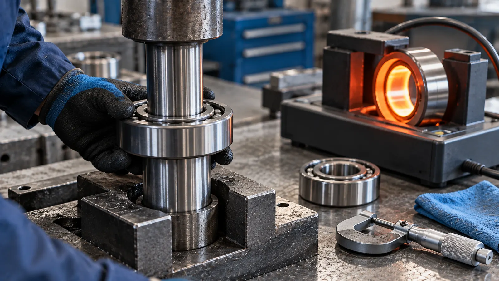
Press only on the ring that has the interference fit. Pushing on the outer ring to fit the inner ring onto a shaft sends the force through the balls, dents the raceways and ruins the bearing.
- Shaft fit: press on the inner ring face with a fitting sleeve or tube that bears on the inner ring only.
- Housing fit: press on the outer ring face only.
- Both rings tight: use a sleeve or disc that bears on both ring faces at once.
- Lubricate the seat with a light oil film and start the bearing square; a cocked ring galls the seat.
- Never hammer the bearing directly. If a mallet is used, strike a fitting sleeve, not the ring.
Heating bearings for mounting
For larger bearings and heavy interference, heat the bearing so it slides on freely. Heat to about 80 to 100 °C (176 to 212 °F) with an induction heater or a temperature-controlled oven, and typically never above 120 °C (248 °F), which risks loss of hardness and dimensional stability. Never use an open flame. Sealed and shielded bearings contain grease and seals with their own limits, so follow the maker's maximum for them. The ring grows by about α × d × ΔT, with α typically about 12 × 10⁻⁶ per °C for bearing steel:
| Bearing | Bore d, mm | Bore growth heated 20 to 100 °C (68 to 212 °F), µm | Largest k6 interference, µm |
|---|---|---|---|
| 6203 | 17 | 16 | 20 |
| 6205 | 25 | 24 | 25 |
| 6208 | 40 | 38 | 30 |
| 6210 | 50 | 48 | 30 |
| 6212 | 60 | 58 | 36 |
On small bearings, heating by 80 °C only about matches the largest k6 interference, so heat is of limited help below about 25 mm bore and a press is normally used. From 40 mm bore up, the same heating opens the bore well past the interference and the bearing slides on freely. Hold the bearing against the shoulder until it cools and grips, or it can pull away from the shoulder as it shrinks axially. For housing fits, the housing can be heated or the bearing cooled instead.
Shaft and housing shoulder heights
Shoulders locate the bearing axially, and their size matters as much as the fit diameter. The shoulder must be high enough to support the full ring face under axial load, but low enough to clear the other ring, the seal and the cage, and to leave part of the ring face exposed for a puller.
- Shoulder diameter: catalogs give a minimum shaft shoulder diameter and a maximum housing shoulder diameter for each bearing. Use them; do not guess from the bore and OD.
- Fillet radius: the shaft or housing fillet radius must be smaller than the bearing's minimum chamfer, so the ring sits fully against the shoulder. Use a relief groove where a larger fillet is needed for strength.
- Square shoulder: the shoulder face must be square to the seat; an out-of-square shoulder tilts the ring and misaligns the bearing.
- Spacers: where a shoulder cannot be machined high enough, use a spacer ring or a locknut and washer.
Correct fits and clearance are what let a bearing reach the life calculated in bearing load ratings and life. Bearing types and their load directions are in types of bearings.
Sources and standards
- ISO 15, Rolling bearings, radial bearings, boundary dimensions, general plan
- ISO 286-1
- ISO 286-2
- ISO 492
- ISO 5753-1
General reference information. When a manufacturer, drawing or governing standard gives a value, that value takes precedence.
Related charts and guides
Common questions
What is a bearing interference fit?
A bearing interference fit is a fit where the shaft is slightly larger than the bearing bore, or the housing slightly smaller than the outside diameter, so the ring must be pressed or heated into place. It stops the ring creeping. For a 6205 with a 25 mm bore on a k5 shaft, the interference is 2 to 21 µm.
What shaft tolerance should I use for a bearing?
For a rotating shaft with a stationary load, common practice is k5 or k6 for normal loads and m5 or m6 for heavier loads or larger shafts, with j5 or j6 for light loads on small shafts. For a 25 mm shaft, k5 is +2 to +11 µm and k6 is +2 to +15 µm. The bearing maker's tables take precedence.
What housing tolerance is used for bearings?
For a stationary outer ring with a rotating shaft, H7 is the standard housing tolerance, with J7 where more accurate radial location is needed. H7 gives a small clearance so the ring can slide axially as the shaft expands. For a rotating outer ring load, such as a wheel on a fixed axle, a tighter N7 or P7 housing is common.
What does C3 clearance mean in a bearing?
C3 means the bearing has more internal radial clearance than normal (CN). It is used when interference fits, a hot shaft or a large temperature difference between the rings would reduce clearance too much, which is common in electric motors. The groups from smallest to largest are C2, CN, C3, C4 and C5, defined in ISO 5753-1.
How do you check bearing clearance?
Clamp the outer ring, place a dial indicator against the inner ring at right angles to the axis, and push the inner ring radially toward and away from the indicator with light force. The difference is the radial play. Repeat at several positions. Large roller bearings are checked with feeler gauges between rollers and outer ring.
What temperature should I heat a bearing to for mounting?
Heat the bearing to about 80 to 100 °C (176 to 212 °F) with an induction heater or controlled oven, and typically never above 120 °C (248 °F). A 40 mm bore heated from 20 to 100 °C grows about 38 µm, more than the largest k6 interference of 30 µm. Never use an open flame, and follow the maker's limit for sealed bearings.
Can you press a bearing on by the outer ring?
No, not when the fit is on the shaft. Pressing on the outer ring to mount the inner ring sends the force through the balls and dents the raceways. Always press on the ring being fitted: the inner ring for a shaft fit, the outer ring for a housing fit, or both rings together with a sleeve that touches both.